BOTTOM HOME
1. Getting rid of the play in the Quill.
2. Installing a Quill Lock.
3. Installing a work light.
I bought a dirt cheap Bench Drill from B&Q well over 10 years ago and it has served me well. I never try and do any precise stuff with it and so do not get disappointed with it.
This Bench Drill is badged Chio. The quality of the castings and equipment on the Drill are not that bad. The downside is that some of the fitting is not as good as it should be and needs a bit of attention.
It is very straightforward to completely strip and reassemble this machine. I gave the coiled Quill Spring the utmost respect and kept my fingers and face out of the way. The Quill Spring Housing only needs about one turn to provide enough tension to return the Quill.
TOP
DEALING WITH A SLOPPY DRILL CHUCK
The 2 journals that support the Quill had worn so much that the drill chuck could be moved 2mm side to side when the Quill was fully extended. The Quill only extends 50mm on this Bench Drill so the 2mm play in the Chuck was huge.
I was on the verge of buying a new Drill Press but decided to see if this one could be fixed first.
↓ Here is the Quill, removed from its housing. The drill chuck fits on the taper on the right hand side of the Quill in this picture.
There was no play at all in the bearings in the Quill.

↓ The Quill is supported and guided by the two Journals you can see here. Each Journal is around 38.9mm in diameter and 11mm deep. The Journals were bored oversized by the makers and so the Bench Drill came with play in the Quill. You get what you pay for.
I decided to cut a slot up the front of the Quill Housing. The Quill Housing can then be squeezed, which will reduce the diameter of the Journals, hence the Quill will fit snuggly in the Journals.
(I took these pictures after I cut the slot in the Quill Housing.)

↓ Here is how I cut the slot.
I supported the Quill Housing on the lathe cross slide table and used a slitting saw in the mill.
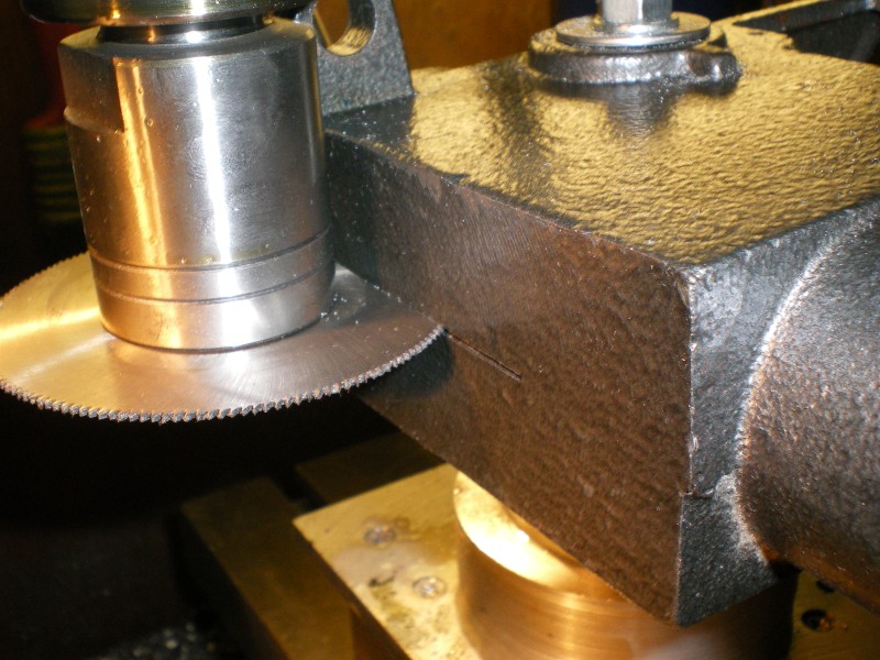

↓ This is the completed slot, right up the front of the Quill Housing. Nice.

↓ I carefully drilled a 6mm diameter hole on the Depth Indicator side of the casting.

↓ I carefully drilled a 6mm diameter hole on the Downfeed Handle side of the casting.

↓ I inserted a length of 6mm threaded rod through the two holes.
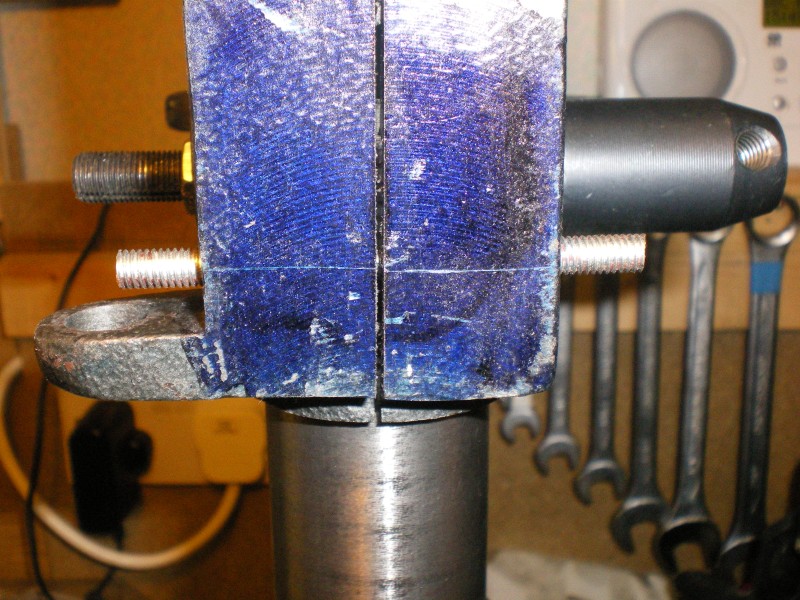
The nuts are tightened and the slot allows the casting to be squeezed.

↓ It only takes a little force to clamp the casting snuggly around the Quill.
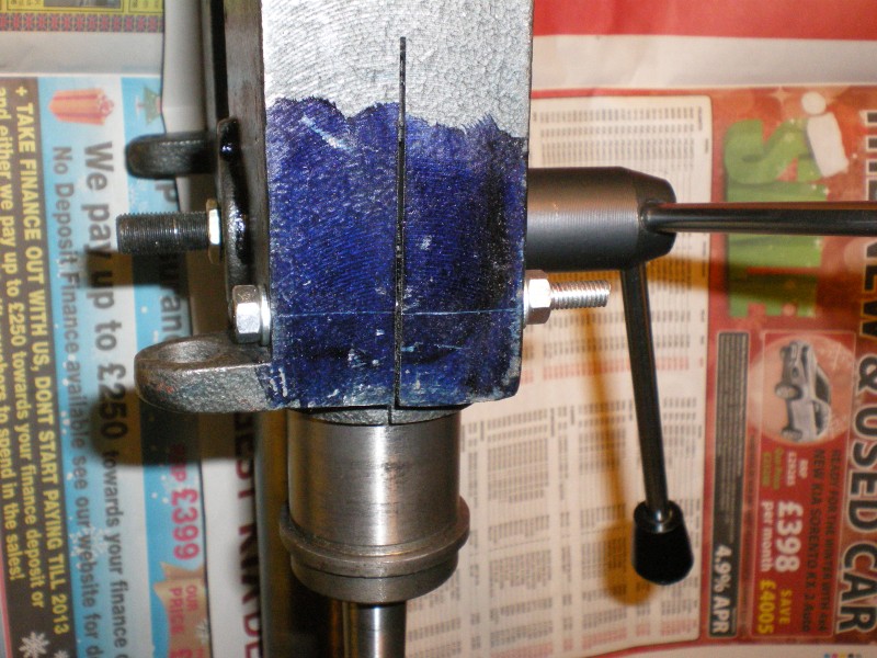
↓ I spent a very long time confirming and marking the hole positions. The threaded rod passes between the casting and the Quill, and it must not foul either.
Here you can see the threaded rod inside the casting.
(Oddly enough, the red oxide paint on the scrap piece of threaded rod matched some red stuff in the housing.)
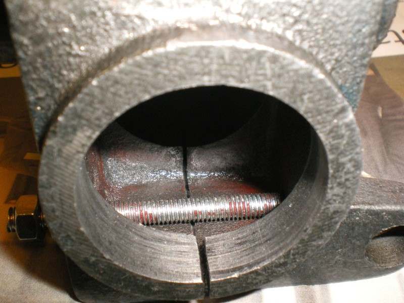
↓ Low and behold the awful play is gone and the Quill moves smoothly up and down. I am very pleased with this and it has given the machine a new lease of life.
The machine now feels nice and tight and positive. It is a pleasure to use.
Time will tell whether this 'slotting' modification provides long service.

TOP
INSTALLING A SIMPLE QUILL LOCK
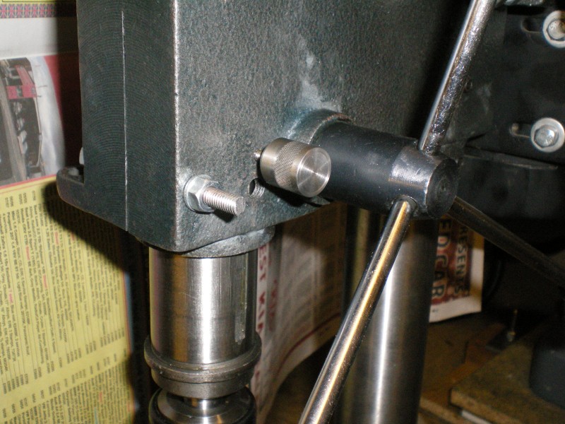
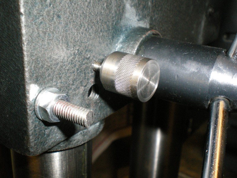
↓ I often have to extend the Quill and hold it in place whilst adjusting the table height to suit a drill bit.
This hand operated Quill Lock is simply a M3 screw with a knurled knob. The end of the screw bears down on the slot in the Quill.
The Quill is held stationary when the screw is tightened against the slot. This leaves two hands free to adjust the table height.
TOP
INSTALLING A WORK LIGHT
I installed a low voltage Ikea Lamp on the Bench Drill.
I have used these lamps quite a lot over the last few years as they give good light, they bend nicely, and they are cheap.
The lamp probably was not a good choice as it created lots of problems during the installation and it took all day to finish. Still, now it is done I am pleased.

↓ The light is 4 volts low voltage and the transformer for it is housed in the moulded plug.
I need the power supply circuit board that is in there.

↓ I used my Black and Decker RT650 rotary power tool to carefully grind away the plastic and expose the transformer circuit board.
These are the 240v Live and Neutral wires.

↓ I found the circuit board. I wore a face mask as this plastic is very dusty.
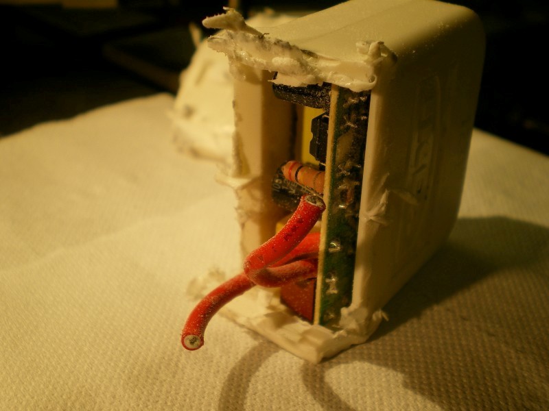
↓ The circuit board is finally out, undamaged.
I touched one of the red wires with the grinding wheel, but it did not cut through the insulation.
The white plug on the right still has to be ground away to expose the low voltage output wires.

↓ I solder 2 lengths of wire to the low voltage outputs on the circuit board. I had to recognise and identify the polarity +/- here.
I crimped Bullet Connectors on the 240v input wires. The input is AC so the polarity is not important here.

↓ I made a box for the circuit board to prevent it shorting out on the Bench Drill.
I cut up a CD case and used the plastic for the box. I think the plastic is polycarbonate, but not too sure.I used Abs/Pvc-U glue to cement it together.

↓ I glued two pieces together, then waited 10 minutes for the glue to set up before handling and gluing up the next piece.
I used a short length of Aluminium angle to help keep the box square while glueing up.
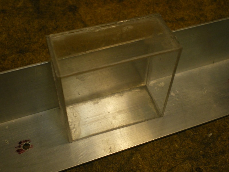
↓ The circuit board fits nicely in the box.
I used a Burr in the Rotary Tool to grind out the holes for the wires. I did not want to run the risk of breaking the plastic with a drill bit.

↓ I used three large blobs of Silicone Sealant to hold the circuit board in the box. I then glued the lid on.
The gluing is a bit messy but the box does the job. I will do better next time.

↓ I had to cut into the existing 240v supply cable to provide a feed for the circuit board and lamp.
I cut the cable, joined the new feed wires to the existing wiring, soldered all the Lives, Neutrals, and Earths together and inserted them in small connector blocks. I protected the connector blocks with the grey heatshrink that you can see in this picture.

↓ I crimped Bullet Connectors on the new feed wires on the right there.
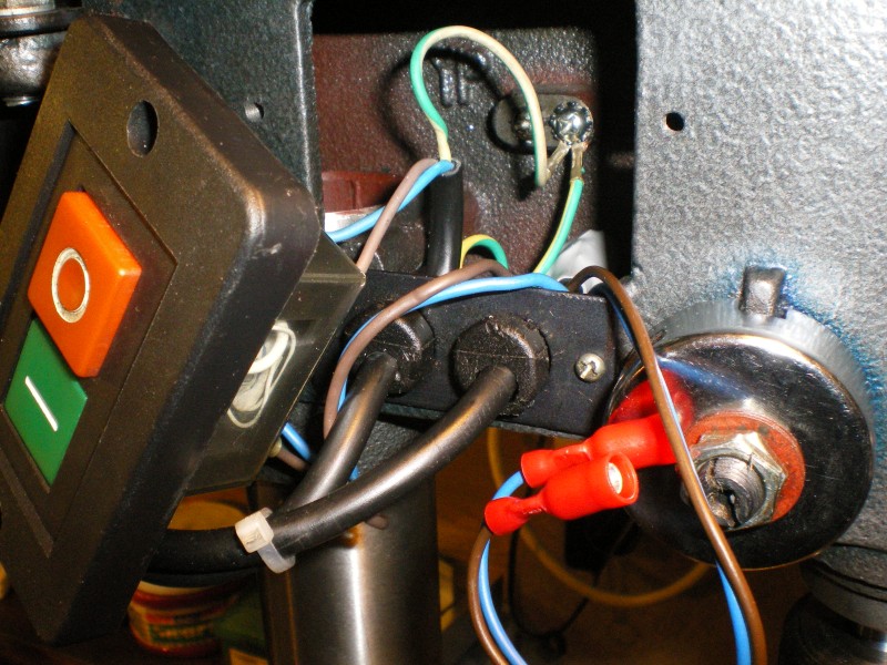
↓ Next I mounted a switch to turn the light on and off.
I drilled a 12mm hole in the casting.
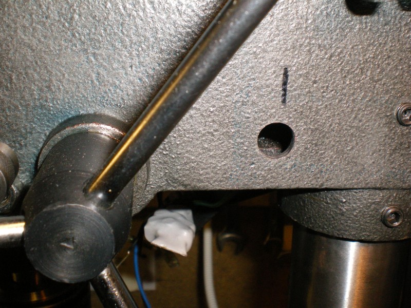
↓ I fed the switch into the hole.

↓ On the other side, I tightened up the nut to secure the switch.
I used some heatshrink to cover up the wiring connection.
This lamp switch is just below the Bench Drill On/Off switch.


↓ Next I mounted the lamp.
I re-routed the lamp wires so they came out of the bottom of the lamp base, rather than through the hole in the side of the base. I did not want any exposed wiring.

↓ I drilled 3 holes in the casting for the lamp.

↓ I fed the wires through the middle hole and secured the lamp to the casting using two M3 machine screws.
I did not take a picture at this stage, but you can see below how the lamp is mounted.

↓ In order to secure the lamp, I had to drill out a couple of nuts and use them as spacers.

↓ I installed the box in the casting. It sits right on top of the column. There was only just enough room for the box.
The lowest red wire coming out of the box is 4volt positive. It goes to the switch and then from the switch it goes to the lamp.
The black wire coming out of the box is negative. It goes directly to the lamp.
The two white wires on the left are the positive and negative feed to the Ikea lamp.
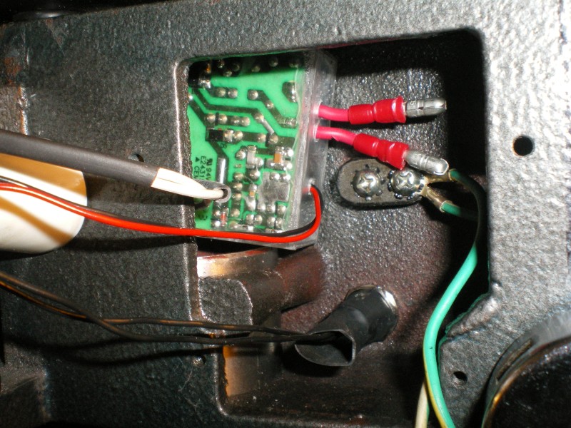
↓ The low voltage wiring can all be tucked down into the column, which makes things very tidy indeed.
You can see the base of the lamp over on the left.
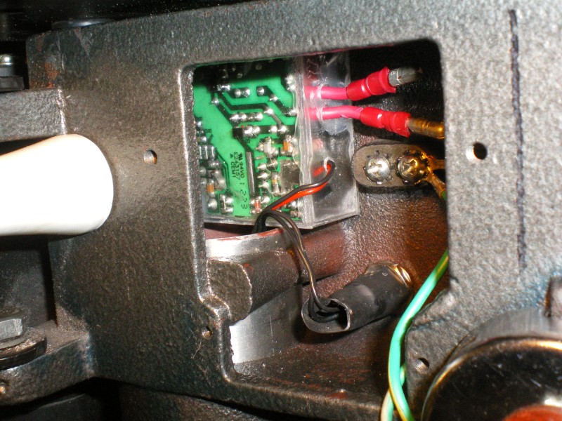
↓ The 240v feed wires are connected to the box.
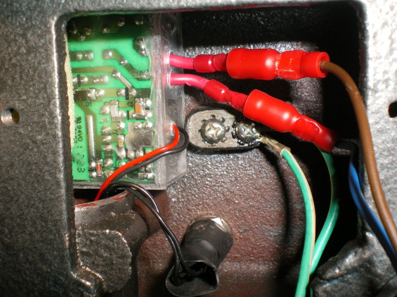
↓ I jammed a large piece of foam into the casting to keep the box in place.

↓ The Bench Drill On/Off switch could not be inserted in the casting, because the circuit board box was now in the way. I had to make a spacer.
I used polypropelene to make the spacer.

↓ It is a bit of a rough job. The whole job was taking a long time and I was now in a hurry to get finished.
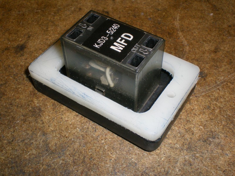

↓ The spacers brings the On/Off switch forwards and still maintains a seal to protect the operator from the wiring behind.

↓ All done, with no extra exposed wiring.
I positioned the lamp so I still had easy access to the motor mounting bolts.
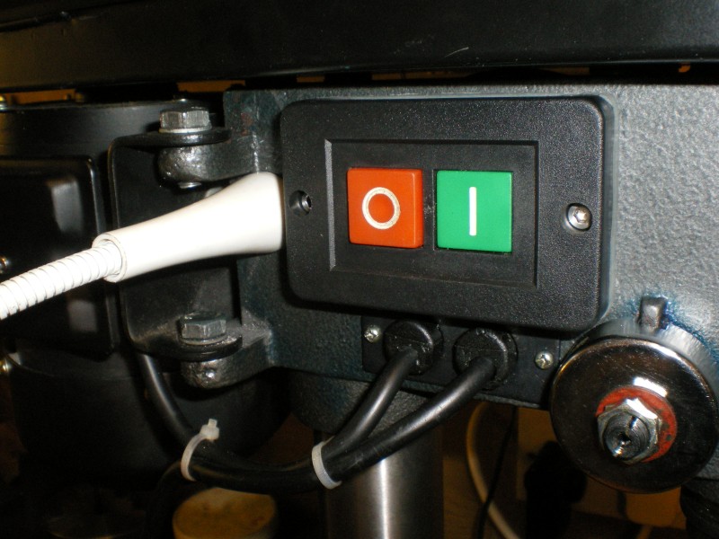
↓ Here is the drill back in its place.
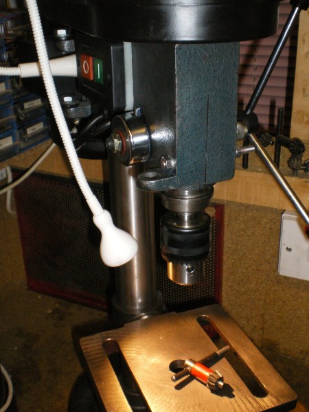
You can see the lamp switch.
I have still got to replace the temporary M6 thread rod that is used to clamp the Quill casting.


UPDATE 09-02-2014
After a while the lamp has started to droop when I position it, which is annoying. This is because I mounted the base of the lamp horizontally, instead of vertically. When I get time I will redo the mounting so that the base of the flexible arm is in the vertical.

TOP HOME


