Clarkson Mark 1 Tool and Cutter Grinder - Relieving End Teeth - End Mill


BOTTOM  HOME


This page details the process I have used to sharpen end mills, following the instructions on page 16 of the Clarkson Operators Handbook.
I have not sharpened many end mills and I am still learning.
I have had to learn the techniques for myself, so my process may not be the best practice. It seems right, my end mills cut, and they last as long as the fresh ones from the suppliers.


TOP

RELIEVING END TEETH - END MILL


Here is my take of page 16 of the Clarkson Mark 1 Operators Handbook.

In my very first attempt at following the instruction, I succeeded in regrinding the teeth on a four flute 12mm end mill. The results were satisfactory. The cutter was rejuvinated and cut through steel in an admirable way. I was very pleased with the initial outcome, to say the least.

I worked my way through the steps outlined on the page 16 of the Operators Handbook, precisely following the instruction.
All was easer said than done, and I had to make use of quite a few fixtures and fittings to help me get through the process. I will point these out along the way.
I work in metric and buy metric tooling. This 1966 Clarkson, and its equipment and tooling, is imperial, which presents many obstacles that have to be overcome. I have a lot of tooling for the machine, but it has to be adapted to the metric system (long live the metric system).

So, let's get started and work our way through the sequence.

Here is the page 16 text:-

The following accessories are required - universal head and bracket, cup type grinding wheel, straight shank cutter holder, adapter bush to suit cutter shank, swan-necked toothrest and type 'F' tooothrest. You will also need some patience.
1. Fit and dress the cup wheel.
2. Swing table into position square to the grinding wheel and lock.
3. Mount universal head and bracket at far end of table, in the manner illustrated.
4. Assemble cutter in adapter and holder.
5. Insert holder etc., into universal head, adjusting collar to give a free running fit.
6. Secure toothrest bracket above universal head, and adjust type 'F' toothrest so that the end tooth to be ground is approximately parallel to the table.
7. Slacken universal head bracket screw and, tilting the end of the cutter upwards, lock the head at 6 degrees.
8. Adjust spindle height so that the grinding wheel clears the lower tooth while covering the tooth to be treated.
9. Set over the top swivel plate slightly, moving the cutter away from the wheel head, to obtain concavity.
10. Take light cuts, indexing from tooth to tooth until all wear is removed, finally taking a light cut all round.
11. Reset universal head to 15 degrees and repeat previous operation (10), this time grinding secondary clearance.


TOP

[1] FIT AND DRESS THE CUP WHEEL.

Contrary to the published sequence. I think that the wheel should be dressed AFTER the table is made square to the grinding wheel (see step 2). So I would do step 2, and then do step 1.

My diamond dresser has a 0.5inch shank. How was I going to hold the dresser and present it to the wheel? This was the first hurdle to over come.
I had the universal head and bracket and a straight shank cutter holder with a 1inch bore. I had two adapter bushes that had an outside diameter of 1inch, and were bored 1/4inch and 3/8th inch. I needed a new adapter bush with a 0.5inch bore.
I had to make a new adaptor bush, with an outside diameter of 1inch to fit in the straight shank cutter, and with a bore of 0.5inch to accept the diamond dressing tool.

Click here for details on making adapter bushes

↓ I copied an existing adaptor bush and made a new one for the dresser bar.
missing image


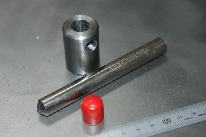
↓ The new adapter bush dimensions are:- length = 1.5inch
od = 1inch
bore = reamed 0.5inch
cross hole diameter = 10mm
cross hole - centre of hole is 10mm from end of bush
missing image


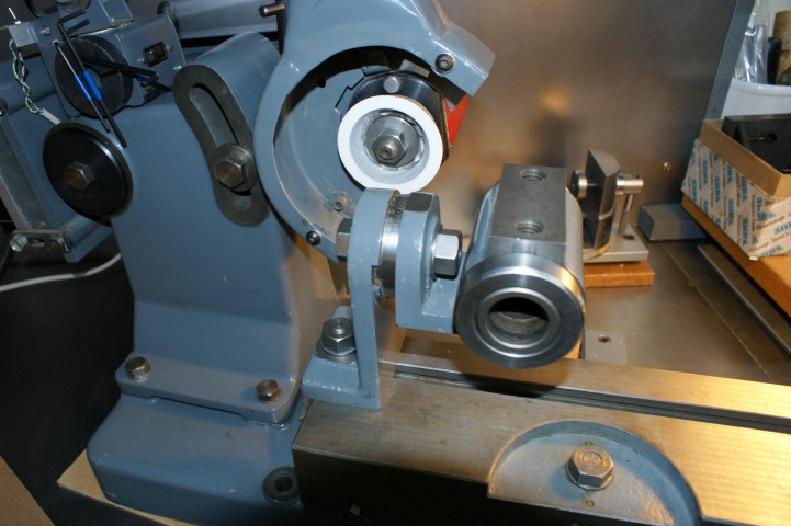
↓ There is a groove in the cup wheel, and that needs to be dressed out.
Notice the reflective pad on the cup wheel. That is a tachometer target that I used to test the rpm of the spindle.
missing image


↓ The wheel is now flat and dressed.
The wheel is 100 grit.
I wore a face mask while dressing.
I placed a hoover nozzle close to the wheel while dressing. The dressing procedure produces a very fine abrasive dust that needs to be contained.
missing image


TOP

[2] SWING TABLE INTO POSITION SQUARE TO THE GRINDING WHEEL AND LOCK.

Another hurdle. How was I going to get the table square to the grinding wheel?

I notice a few Clarkson owners get the table square to the grinding wheel and then drill a hole in the base plate of the table and fit a pin. The pin allows the base plate to be easily rotated and indexed, to bring the table square. I did not want to alter the Clarkson at the time so came up with another arrangement.
I also did not fit a pin at this stage because the bolt that secures the rotating base plate is not a tight fit in the hole of the base plate. Hence, the base plate can be pushed off centre due to the play between the bolt and the hole. This play makes things slightly inaccurate. I will make a tight fitting bolt at a later date.

↓ I fitted a 'wide' grinding wheel on the spindle. The 6inch wide grinding wheel gave me a long surface to square up to.
I secured an angle plate to the table. I aligned the angle plate with the edge of the table, using the engineers square you can see in the picture.
Once the angle plate was secured to the table, I adjusted the position of the table so that the angle plate was flush on the grinding wheel. This squared up the table to the spindle.


missing image
TOP

[3] MOUNT UNIVERSAL HEAD AND BRACKET AT FAR END OF TABLE, IN THE MANNER ILLUSTRATED.

↓ Notice that my bracket is overhanging the edge of the table. That's a mistake.
missing image
TOP

[4] ASSEMBLE CUTTER IN ADAPTER AND HOLDER.

My end mill shafts are metric. How was I going to hold the end mills and present them the wheel? Yet another hurdle.
I had to make two new adaptor bushes, with an outside diameter of 1inch to fit in the straight shank cutter, and with a bore of 10mm and 12mm to accept my end mills.

Click here for details on making adapter bushes

I am not too sure how the holder and adapter are assembled, so stand to be corrected here.
It looks like the hex set screw in the holder, passes through the cross hole in the adapter bush, and bears down on the shank of the cutter. Thus the shank, bush, and cutter and held together as one.
It does not seem right that the end of the hex set screw bears down on the shank of the cutter. To play safe, I inserted a ball, and the smooth surface of the ball bears against the cutter shank. I might be widly wrong with this assembly, but my method works.


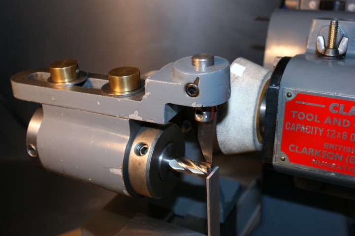
↓ The cutter is located in the adapter bush.
I have inserted a ball in the adapter cross hole.
missing image


missing image


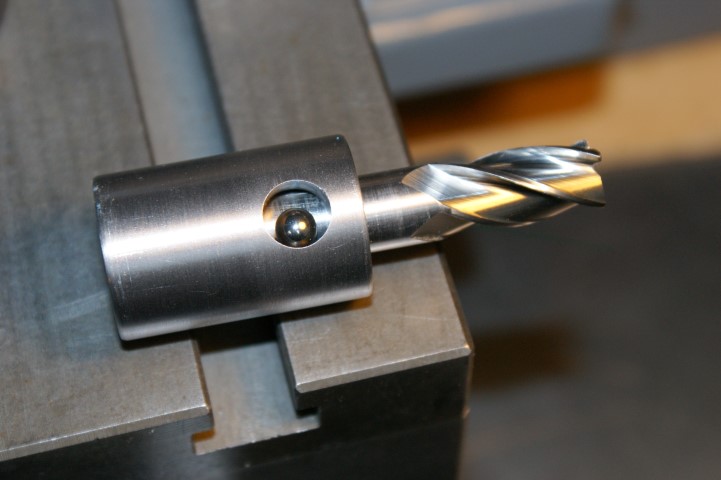
↓ The adapter bush is inserted into the holder.
missing image


missing image


↓ The cross hole in the adapter bush is lined up with the threaded hole in the holder.
missing image


↓ The cutter is positioned, taking care to ensure that the ball does not bear down on the threaded end of the cutter (if threaded end is present).
missing image


↓ The hex set screw is inserted in the threaded hole of the holder, and is gently and carefully tightened, to bring the assembly together.
missing image


TOP

[5] INSERT HOLDER ETC., INTO UNIVERSAL HEAD, ADJUSTING COLLARS TO GIVE A FREE RUNNING FIT.

↓ The holder is inserted into the Universal Head.
missing image


missing image


↓ A collar is fitted.
The teeth will not form correctly if there is any movement in the holder when grinding.
The collar, shown on the left, is tightened to ensure that there is no end float in the holder.
The holder can be rotated, to allow each tooth to be indexed.
A tooth rest prevents the holder from rotating when grinding.
missing image


TOP

[6] SECURE TOOTHREST BRACKET ABOVE UNIVERSAL HEAD, AND ADJUST TYPE 'F' TOOTHREST SO THAT THE END TOOTH TO BE GROUND IS APPROXIMATELY PARALLEL TO THE TABLE.


How can I set the end tooth so that it roughly parallel to the top of the table?
I cannot posibly line it up by eye, that is too inaccurate for me.
I eventually made an 'end tooth setting tool' to deal with the problem. I call it a cutter setter.

↓ Here is the cutter setter.
missing image


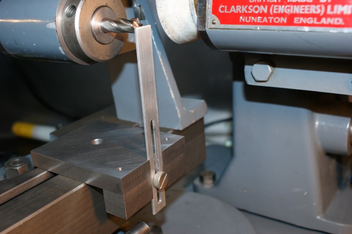
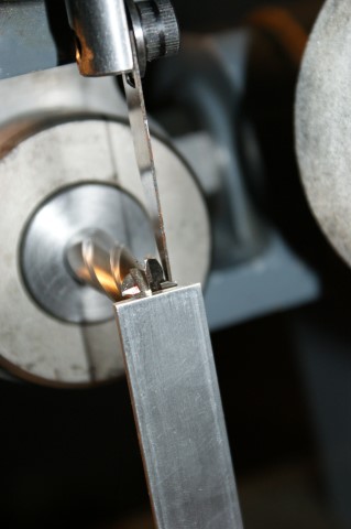
↓ The slotted guide can be moved up or down to suit the situation.
The slotted guide is perpendicular to the table top.
missing image


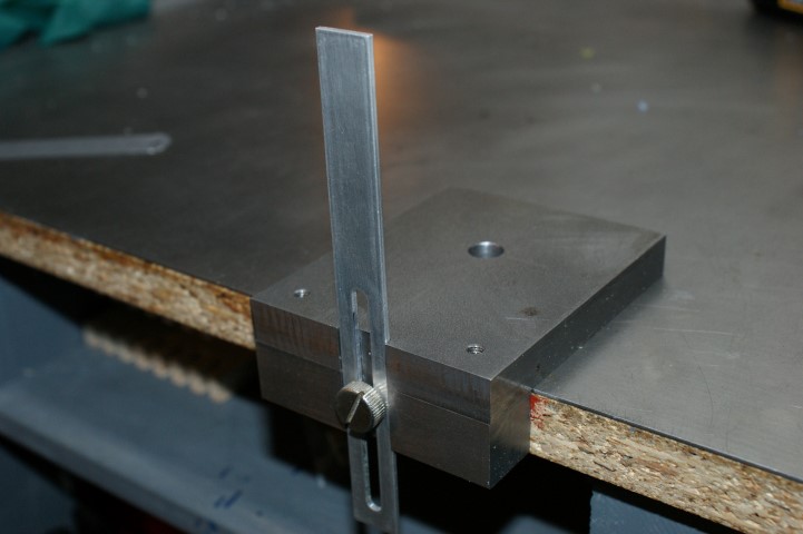
↓ The teeth are lined up to the end of the slotted guide.
missing image


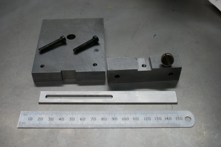
↓ Here are the parts of the cutter setter.
missing image


↓ Once the teeth are roughly parallel with the table, the toothrest bracket and toothrest finger are adjusted and secured so that the end mill is prevented from turning.
When grinding on the right side of the cup wheel the wheel direction is up, and this action presses the end mill tooth upwards against the toothrest finger.
missing image


missing image


missing image


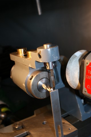
↓ Make sure the bracket is secure and will not come loose during the whole operation.
missing image


missing image


missing image


missing image


missing image


missing image


A finger needs to be flexible. Once the finger is fitting snuggly in a flute of the end mill, you should be able to gently and slowly rotate the holder, one tooth at a time to perform the indexing operation. As you rotate the holder, the finger is pushed out of the flute, and then clicks into the next flute as the next tooth comes around to the horizontal position. Once it has clicked back into a flute, the finger holds the end mill steady during the grinding pass.
The first finger I made was not 'springy' enough, and was too thick and stiff. Hacksaw blade material works for me.

↓ The upper finger was made by the University department that sold the machine to me.
The bottom 2 fingers are homemade F types (similar to part number 93547).
The middle finger is too thick and not very flexible.
The lower finger is made from a hacksaw blade, and is just right.
The longest straight edge on the F type goes towards the wheel.
Note the angles on the ends of the fingers. The angle end rests on the slope in a flute.
missing image


TOP

[7] SLACKEN UNIVERSAL HEAD BRACKET SCREW AND, TILTING THE END OF THE CUTTER UPWARDS, LOCK THE HEAD AT 6 DEGREES.


↓ Setting the cutter upwards and setting it at 6 degrees.
The divisions on the scale are at 2.5 degree intervals. I set the head to somewhere between 5 degrees and 7.5degrees.
If the angle is slightly out then it is not a big concern. If all the teeth are ground at one setting, then all will be good. missing image


missing image


missing image


missing image


missing image


missing image


TOP

[8] ADJUST SPINDLE HEIGHT SO THAT THE GRINDING WHEEL CLEARS THE LOWER TOOTH WHILE COVERING THE TOOTH TO BE TREATED.


I adjusted the wheel height so that the horizontal tooth to be sharpened was the only tooth contacting the wheel.
When feeding the tooth into and across the wheel, I had to stop as the wheel approached the centre of the end mill, to avoid grinding the tooth on the opposite side to the one being ground.


TOP

[9] SET OVER THE TOP SWIVEL PLATE SLIGHTLY, MOVING THE CUTTER AWAY FROM THE WHEEL HEAD, TO OBTAIN CONCAVITY.


The teeth of the end mill are angled in towards the centre of the cutter. The inside end of a tooth is lower than the outside end of the tooth (concavity).
The table does not have to be set over by much. I experimented a bit with this setting.

↓ The table position before it was set over.
Please note the right hand vertical edge.
missing image


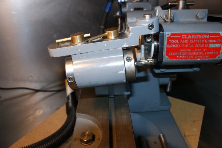
↓ The table position after it was set over by a little bit.
missing image


↓ The table position after it was set over by a lot.
missing image


TOP

[10] TAKE LIGHT CUTS, INDEXING FROM TOOTH TO TOOTH UNTIL ALL WEAR IS REMOVED, FINALLY TAKING A LIGHT CUT ALL ROUND.


My eye sight is poor and have to use an Optivisor with a high powered lens in order to see anything close up.
Because the focal length of the Optivisor lens is so short, my eyes have to be about 100mm away from the object I am inspecting.
This means that my eyes are extremely close to the rotating cup wheel, as I watch as I pass the edges of the cutter across the face of the cup wheel.

I have not had a wheel explode on me in 50 years. I did have a lathe tool dig in badly once, and that chipped a big chunk off a wheel (luckily the wheel did not disintegrate)
For extra safety, and peace of mind, I made a shield. I hope it goes some way to lessen the severity of the airborne fragments of a disintegrating wheel (when it occurs).

↓ The two rods are 0.5inch diameter. They are each tapped M5, to accept a thumb screw.
I used a burr to 'melt' the two holes in the plastic. A drill would have split the plastic and wrecked it.
missing image


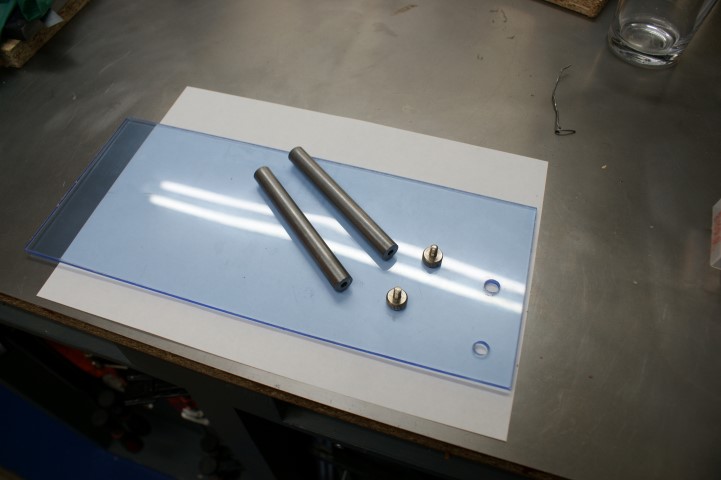
↓ The two M5 thumb screws.
missing image


↓ It needed some large washers to spread the load.
missing image


missing image


missing image


missing image


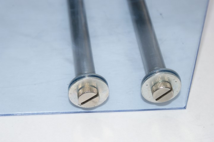
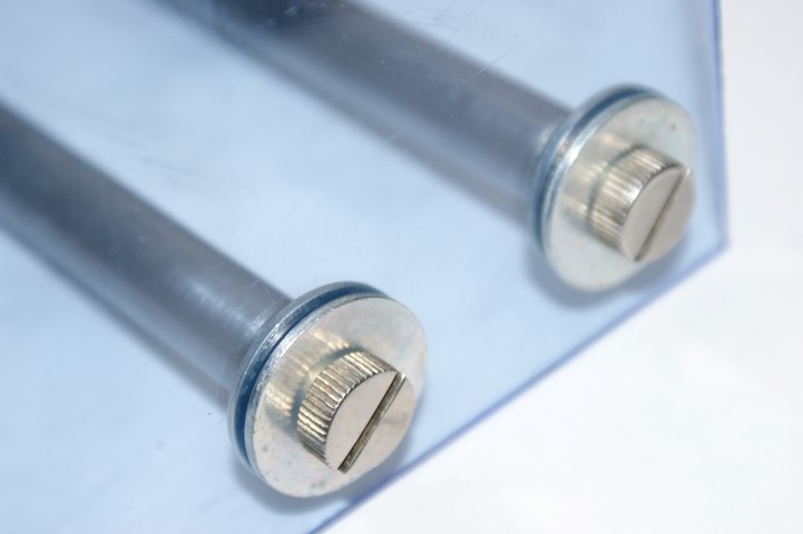
↓ The two 0.5inch bars fit in the lower toothrest mounting block.
The bars are each held in the mounting block by a hex set screw.
missing image


missing image


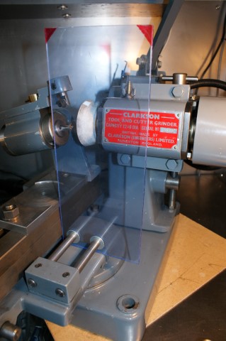
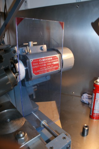
Now, my layers of eye protection are ... the shield next to the grinding wheel, then the optivisor lenses, then my safety glasses, then my seeing glasses.
If a fragment gets through all those layers then I am doomed.


TOP

[11] RESET UNIVERSAL HEAD TO 15 DEGREES AND REPEAT PREVIOUS OPERATION (10), THIS TIME GRINDING SECONDARY CLEARANCE.


This is the same as operation [7], except the head is tilted up to a 15 degree angle.

Some end mills I have sharpened have had a much steeper secondary relief angle, and the angle was around 25 degrees on one end mill I had.


missing image


missing image


missing image


missing image


TOP


After regrindingthe end teeth I found I did not thin wheel with which to gash the end teeth. Instead, I held the cutter in the bench vice and used a thin 25mm diameter cutting wheel in a rotary tool (like a dremel) to gash the end freehand. The gashing turned out ok, but was not perfect.


The next thing I need to learn is to regrind the primary and secondary faces on the flutes. It looks like I need to get a 6 inch wheel for that operation.


Valid HTML 4.01 Transitional

TOP  HOME