LATHE CROSS DRILLING FIXTURE

Warco WMT300/2 (similar to the Clarke, Grizzly 4015 and Smithy 1220)


BOTTOM  HOME


Here is a fixture to enable quick and accurate cross drilling in circular parts.
The V Blocks are permanently aligned to the lathe center height and this greatly reduces the time spent measuring and aligning.

The fixture does not demand great accuracy in the making, but things are easier if you are extremely exact.
The V Blocks must be aligned to each other. The V Blocks must be aligned to the lathe center height.


All I have to do is:

1. Bolt the fixture to the cross slide using the two bolts as shown.
2. Align the fixture on the cross slide using a DTI.
3. Clamp the work in the V Blocks.
4. Drill away.


missing image


missing image

↓ For accuracy, I used a matched pair of off the shelf V Blocks.
In each block, I drilled four holes and tapped them M6 to a depth of 15mm.
I had trouble drilling the holes because the outer surface (about 1mm) of the V Blocks was hardened.
I ruined 4 HSS drills trying to break through the top surface.
Eventually I purchased a carbide drill and used it to break through the top surface. I was then able to drill freely with the HSS drill bits.

missing image
Top

↓ I drilled 8 holes in a plate.
The V Blocks will be secured to this plate.
The V Blocks must be perfectly aligned with each other on the plate.
If the V Blocks will not align then one or more holes must be drilled 'slightly' oversized.
I laid out the holes on the plate and V Blocks very accurately.
I just drilled the holes 6mm in the plate, and this seems to have provided the necessary play.

missing image


missing image


missing image
↓ I counterbored the 8 holes so that the M6 hex cap screw heads would end up below the surface of the plate.
I aligned the mill to each hole using a 6mm diameter peg held in the posilock collet chuck.

missing image


missing image
↓ I used an 10mm end mill to make the bores for the caps of the M6 cap screws.
I will get me some of those counterbore drills at some point.
missing image
Top

↓ The V Block support plate will be attached to an off the shelf angle plate using two M8 bolts.
I bought a chinese angle plate and, being dissatisfied with it, I have no qualms about using it permanently on this fixture.

missing image
↓ Two holes were drilled and tapped M8. These are used when securing the V Block support plate to the angle plate.
The holes are under the middle of the Vs of the V Blocks.

missing image


missing image


missing image
↓ The V Blocks were secured to the V Block support plate using 8 M6 hex cap head screws.
Before the screws were fully tightened a 25mm dia bar was pressed onto the V Blocks so that they became perfectly aligned.
When the V Blocks were aligned their screws were fully tightened.
As long as the V Blocks are aligned with each other, it does not matter if they are not aligned perfectly square to the support plate.
The V Blocks must be perfectly aligned with each other.
missing image


missing image
Top

↓ The work needs to be secured in the V Blocks somehow. The clamps that came with the V Blocks will foul in the lathe chuck, so I dispensed with those and made some custom clamps.
I made four posts and tapped them M6. The clamps that secure the work in the V Block will screw into the M6 threaded posts.
The four posts are roughly cut to size and bored all the way through.
The four posts are then tapped M6, all the way through.

missing image


missing image
↓ The posts are faced on one end and then marked, ready to be trimmed to final size.
I messed up the posts while tapping them in the lathe. They turned in the chuck and got scored.
Oh well, I must press on and see if the whole idea works. I must not rush.
missing image


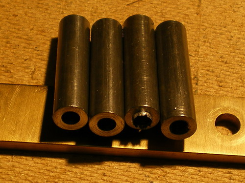
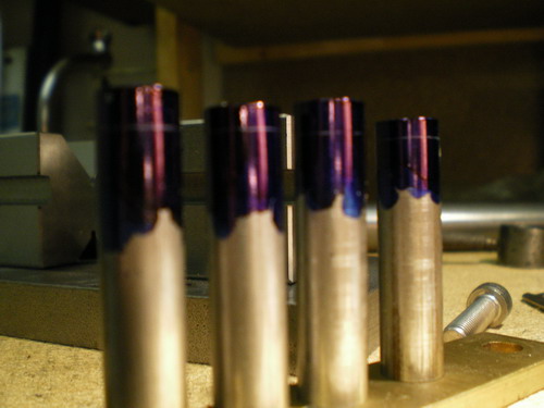
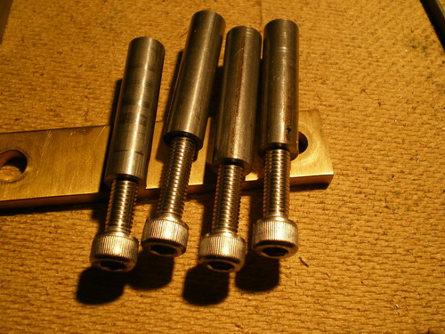
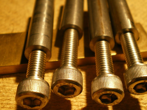
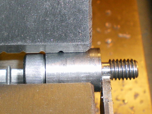
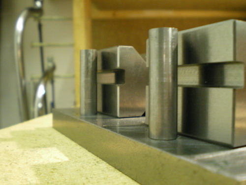
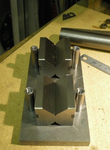
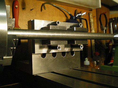
↓ I made a couple of sets of M6 cap screws, of varying length, to fit the posts.
missing image


missing image
↓ I made a button of the correct length to hold the M6 cap screws in the lathe chuck and cut the screws to length using a parting off tool.
I then tarted up the screw ends in the lathe.
Note the button in the jaws prevents the jaws touching the cap head.
This shows the screw being parted off.
missing image


missing image
↓ The four posts will be positioned alongside each V Block and secured to the plate with M6 studding.
Here are the holes for the studding being drilled and tapped.
missing image


missing image
↓ So, the 8 counterbored holes are used to secure the V Blocks.
The 4 M6 holes are used to secure the clamp posts.
The 2 M8 holes are used to secure this plate to the angle plate.
missing image
↓ Here are the posts attached to the plate.
Each post is secured to the plate with a short length of M6 studding.
I superglued the studding in each post.
The posts are secured very tightly to the plate.
missing image


missing image


missing image
Top

↓ Some securing clamp plates were made to fit the posts.
I used some some brass bars from an earlier attempt, hence the extra hole in the top of each bar.
missing image


missing image
↓ Here is a small bar being held.
There should be a shim between the screw and work.
missing image
↓ Here is a large piece being held.
Note the long studs in the posts.
missing image
Top

↓ The V Block support plate is secured to the angle plate by M8 bolts and a bar.
missing image


missing image
Top

↓ The angle plate is lightly bolted to the cross slide. The angle plate can move about, but cannot lift.
The support plate, holding the two V Blocks, is lightly bolted to the angle plate, using the two M8 bolts and bar. The support plate can move about, but cannot lift off the angle plate.
A large bar is inserted in the lathe chuck and trued up to be on center.
The V Blocks are then pressed against the bar in the lathe chuck. The V Blocks are brought on center with the lathe center.
The M8 bolts are then tightened up so the V Block support plate is held very tight.
Any bar held in the V Blocks should now be horizontal and on center with the lathe center.
missing image


missing image


missing image


missing image


missing image


missing image
Top

↓ Here is the fixture being set up on the cross slide.
The bottom of the angle plate is lined up to the cross slide .
missing image


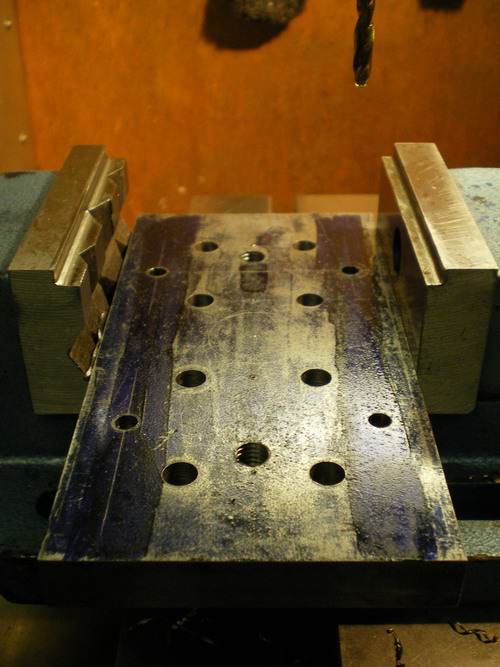
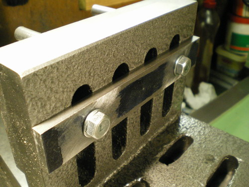
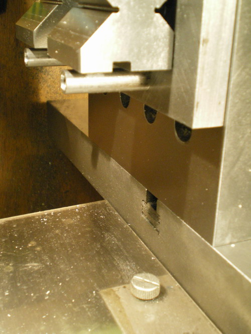
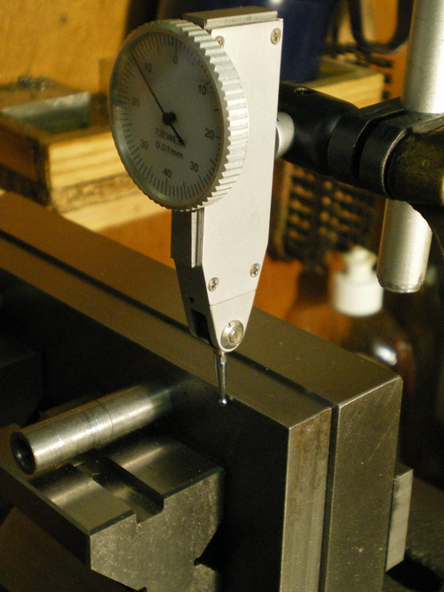
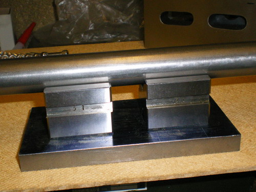
The DTI is set up. The cross slide is run in and out. The fixture is repositioned until the DTI reads zero deviation.
missing image


missing image


missing image
Top

↓ I did some tests to make sure the fixture was aligned correctly.
In one test I clamped a length of 19mm square stock, and drilled from one corner to the other.
This is a 4mm drill bit going into a center drilled hole.
missing image


missing image


missing image


missing image
↓ The drill has exited the other end. Woo hoo, it came out on target. How could it not?
missing image
↓ Here is a 4mm rod inserted in the hole. There are drill tests in this rod.
missing image
Top


↓ It looks like a goer. After hastily putting it together to see if it would work I now have to go over it again and tidy it up.
The edges of the plates are poor. I have an unused inverted dovetail cutter that I am going to try out on the edges.
missing image
I've got some ideas for some extra fittings to allow the work to be accurately rotated in the V Blocks.
If the work can be drilled, then accurately rotated, and then drilled again, it will be possible to cross drill 2,4,6, and 8 holes quickly and neatly in a bar.


Valid HTML 4.01 Transitional

TOP  HOME