| ROUTER TABLE - Mark 2 - Under Construction |
↓ Here are the Kreg adjusters. I did not duplicate these, I just used the idea.

I cut the blanks for my four adjusters out of an offcut of 1/4inch mild steel plate.

↓ Before separating the four pieces I drilled all the holes in one go.

↓ I separated the four pieces and tapped the 8 off M4 threaded holes individually.

↓ The corners were too sharp. I did not have time to round them off using the rotary table so I cut each corner at 45 degrees.

↓ Here they are after shaping, still pinned together by 2 brass pins.

↓ Here they are separated and finished for now.


↓ This is one of the four brackets with all its' adjuster screws and wood screws.


↓ This is a view of the top of table with the Insert Plate in the recess and showing the four brackets that will be fitted underneath to keep the Insert Plate flush with the table top.

↓ This is a view of the underside of the Insert Plate in the recess.

↓ Here are the brackets in the recess in the table.

↓ Here are all four brackets fixed in position on the underside of the table.

↓ Here is a close up of one of the adjuster brackets.


↓ I transferred the four 5mm hole positions from the router base onto the Insert Plate. I then very carefully drilled the four 5mm holes and countersunk them.

↓ The four M5 countersunk screws are loosely inserted into the Insert Plate.

↓ After a couple of unsatisfactory attempts at fixing the router base to the Insert Plate I ended up spending a lot of time making two proper brackets.


↓ The routerbase is positioned over the four M5 countersunk screws.


↓ The first bracket is fitted.

↓ The other bracket is fitted.

↓ I'm pleased that this fixing method turmed out ok. It was well worth the extra time making the brackets.

↓ The router is now firmly fixed to the Insert Plate.


↓ This block was a touch too large, so I cut a sliver off in the bandsaw. I just love my Clarke bandsaw.


↓ I machined the block to fit in the tight space between the bracket and the router bellows.

↓ The block will be secured to the base using an M5 screw passing through the larger hole B.

↓ This is the underside of the router base.

↓ I drilled and reamed a 10mm and a 5mm hole in the block. I had to be as accurate as I could be on this job.

↓ Here is the blank 10mm shaft inserted in the block. It is a very good fit.

↓ Here is the block and blank shaft positioned on the router.


↓ I had to cut an M10 thread on one end of the shaft.

↓ Just as I was nearing completion I ran the cutting tool into the centre in the tail stock and broke the 60 degree tip.

↓ The block was cut down.

↓ I made a phosphor bronze bush to fit the 10mm reamed hole in the block.

↓ I pressed the bush into the block. Nice.

↓ I machined the end of the shaft to fit inside the bush.


↓ The hex drive section is brazed (silver solder) into the end of the shaft.

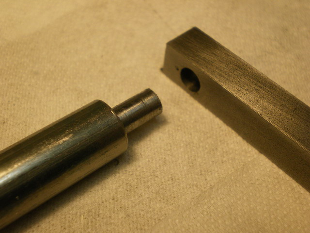
↓ Here is the shaft end inserted in the bush in the block.

↓ Here is the shaft mounted on the router.

↓ The shaft needs to be fixed in position so that it does not move up or down.

↓ After the trial fits I machined the block and the locking piece to a more reasonable size.

↓ Here is the shaft assembly sitting on a v-block.

↓ Here is the shaft assembly fitted to the router.


↓ I cut up a 10mm diameter bar 250mm long.


↓ There are quite a few bits to this simple job that took all day.

↓ This is the knob that is used to turn the crank.

↓ This is the 10mm diameter shaft that the knob is fixed to.

↓ Here is the knob on the shaft.


↓ Here is the main shaft and the shaft sleeve.

↓ Here is the sleeve on the main shaft, snugged up against the socket that has been brazed onto the end of the main shaft.


↓ The end of the main shaft is turned down to 6mm diameter, to fit in the 6mm hole in the square section link.
↓ The end of the knob shaft is turned down to 6mm diameter, to fit in the 6mm hole in the square section link.

↓ Here is a trial assembly of the parts.

↓ I quickly put a radius on each end of the square section link. I did this free hand on the linisher and it turned out very accurate.

↓ I gave it a coat of B&Q hammered paint. The paint still feels soft even after a few days. It will have to do for now. It is only a cranking handle.


↓ Here you can see the sleeve that is free to turn on the shaft.

↓ Here is the finished crank. It is a bit bulky, but it works well. I will make a more delicately proportioned smaller crank when I have a bit of time to spare.