| TAPPING GUIDES - HOME MADE |
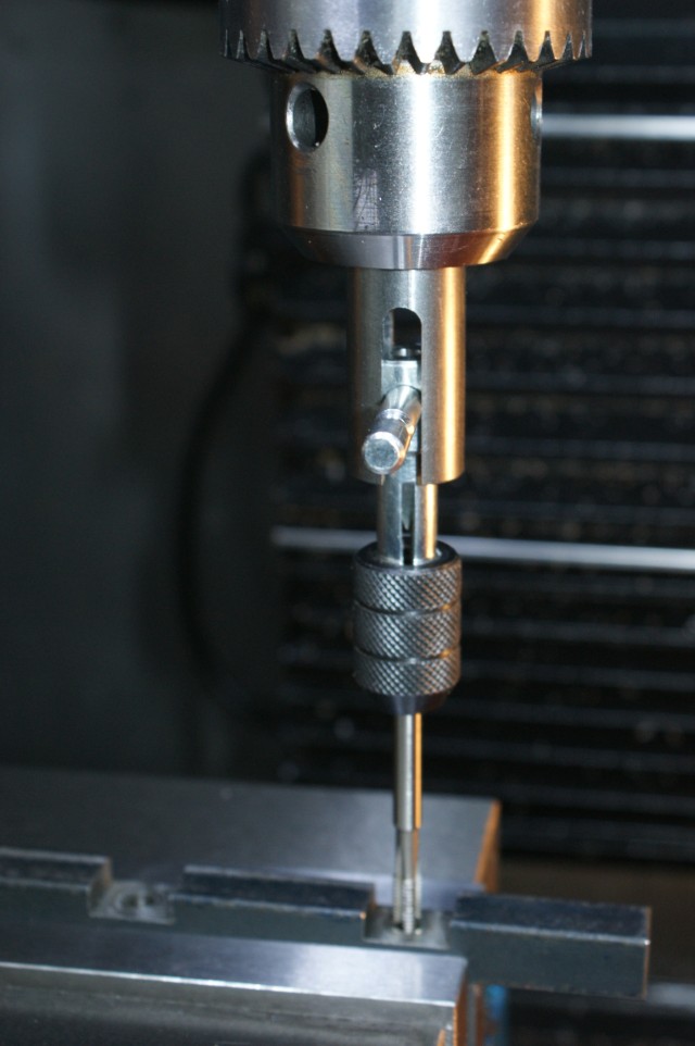
↓ 1. Spring Loaded Tap Guide.

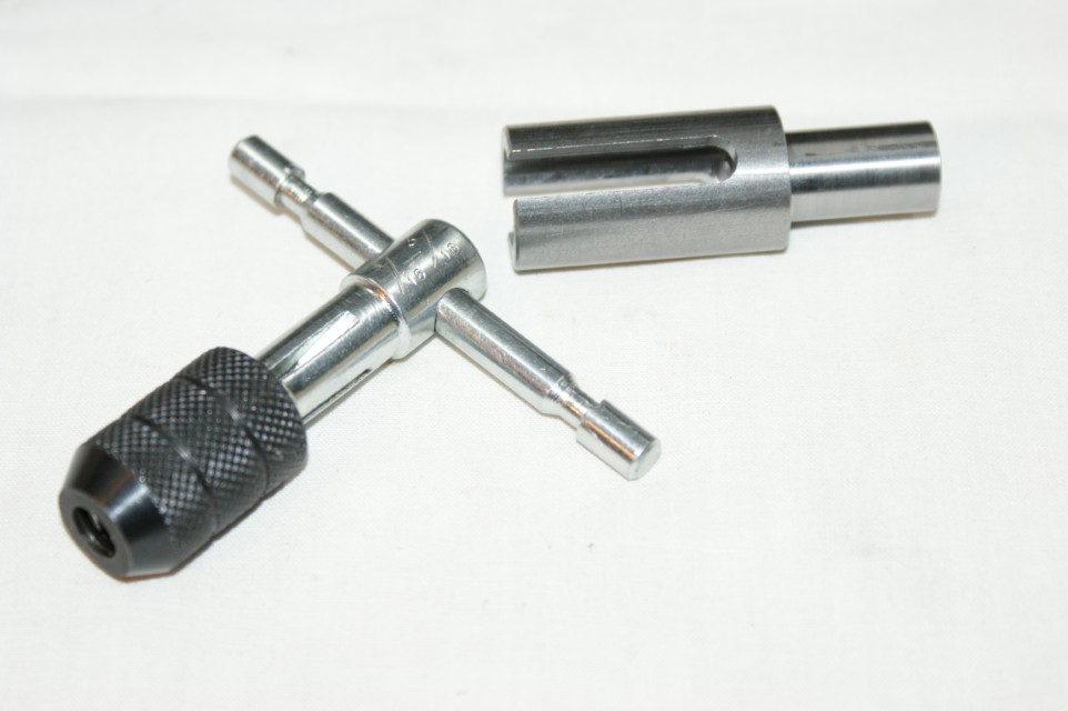
↓ 2. Tap Guide Sleeves.
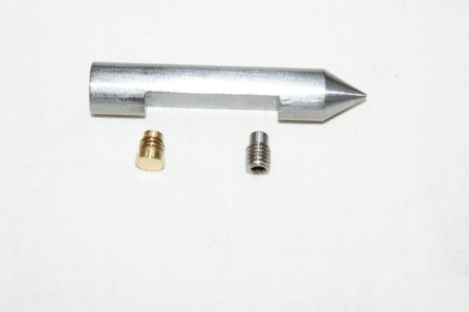
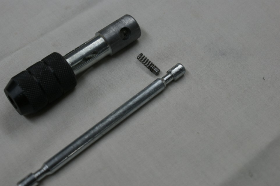
↓ Here are the parts that are very easy to make.
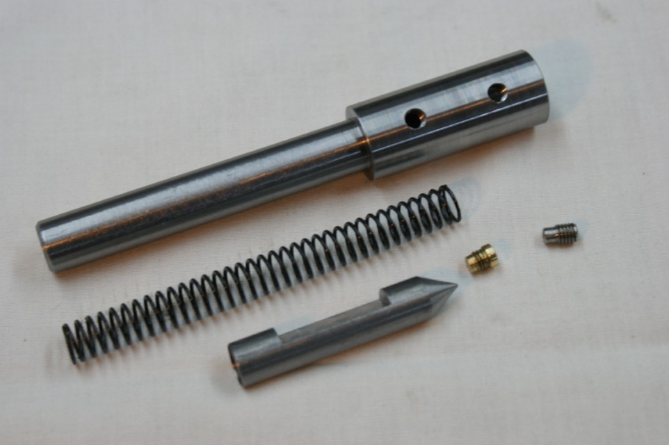
↓ The dimensions in mm are:-
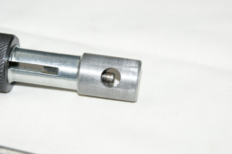
↓ Construction notes:-
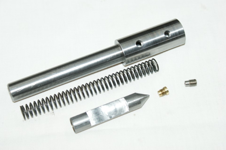

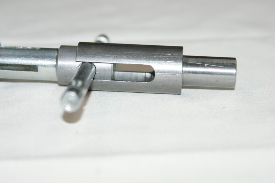
↓ The two set screws catch the barrel at either end of the flat portion, and stop the motion of the barrel.


↓ Here is the guide in the storage tray, in the unextended state.
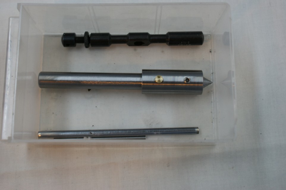
↓ The barrel travel is 22mm.
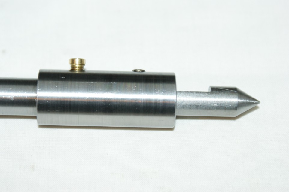
↓ Here is the guide in the unextended state.
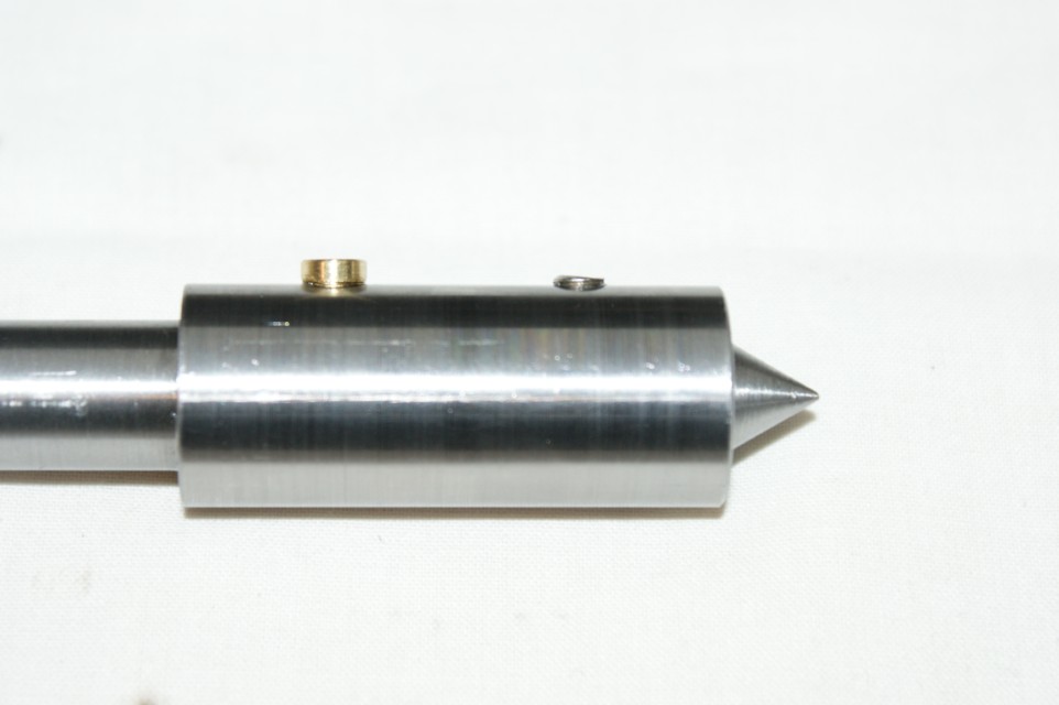
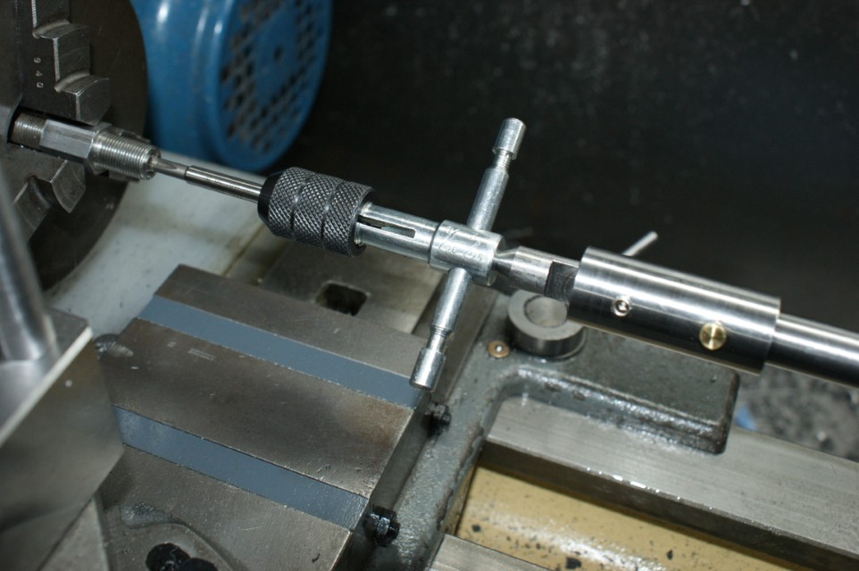
The tapping is complete and the barrel has moved out of the body during the operation.
↓ I bought the 'T-Handle Tap Wrench Set of 4 - 1/16 to 1/2 - 060-250-02500' from ArcEuroTrade.

I made some tap guide sleeves to fit the 3 smaller sizes in the set.
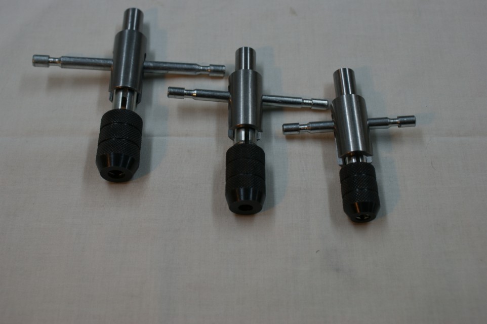
↓ Here is a tap wrench and sleeve.
↓ The tap wrenches in the set vary in size, so the dimensions of the 3 sleeves vary in size.

↓ Sleeve on the tap wrench.
↓ NB: I did not make the bore deep enough.

↓ I was impressed with the quality of the ArcEuroTrade set.

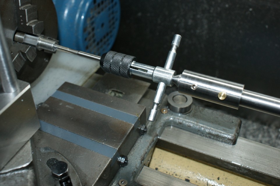
↓ Here is a bar being tapped M6.
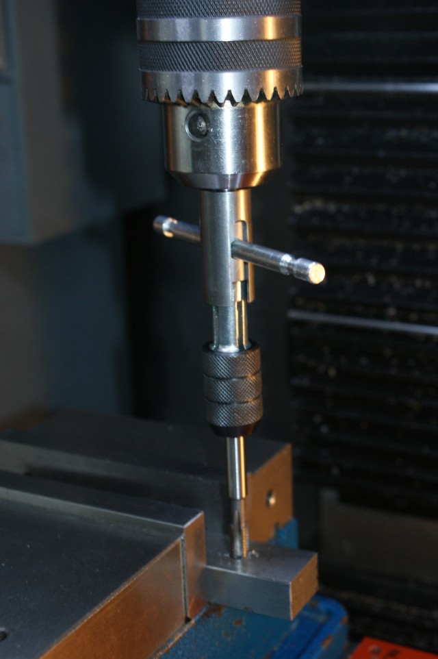
↓ Here is a bar being tapped M5.